The JAMS diagram function provides a graphical representation of the framework and relationships that make up a Setups and Job definition. JAMS diagrams are dynamic, allowing users to modify Setups and Jobs from within the diagram itself to allow you to add Jobs, Dependencies and Resources. Diagrams can also be reproduced using formatting and printing controls.
JAMS diagrams comes in two flavors: a Definitions Diagram and Scheduled Jobs Diagram. While both types have their similarities in form, each provides a different perspective on how various JAMS elements are presented.
A Definition Diagram allows the user to graphically view a Setup's detailed and often complex relationship wit its component Jobs and Dependencies.
To manually generate a Definition Diagram . . .
- Open the Setup Definitions View and right-click on a Setup.
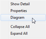
- Right-click and on the context menu choose the Diagram command.

Definition Diagram Elements
The Definition Diagram provides a bird’s eye view showing how each Job will execute within a Setup.
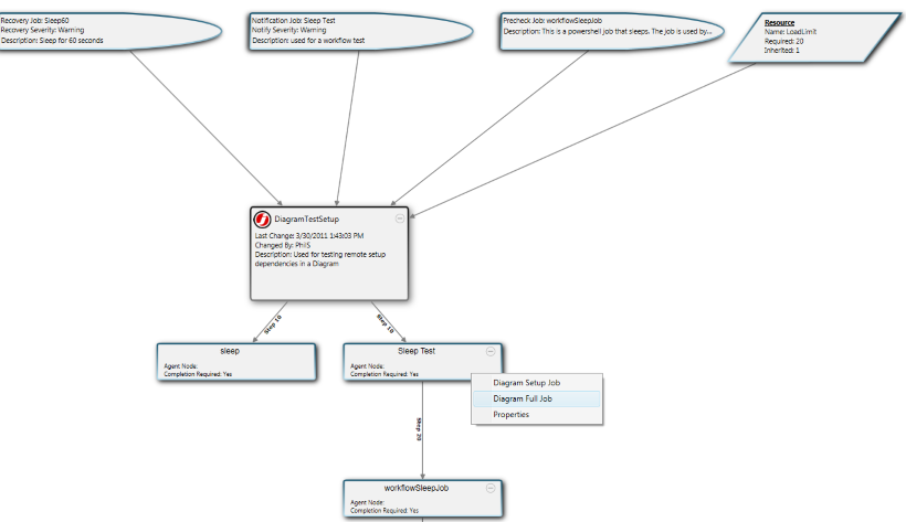
The top portion of a Setup diagram can include representations of Pre-check Jobs (user defined prerequisites), recovery actions, notification details, Dependencies and Resources. Moving down the diagram hierarchy, these objects are then linked to individual Job definitions.
Detailed Setup information along with its component Jobs and Dependencies can be viewed and modified by accessing its property window (right-clicking the object and selecting the Properties command).
The Definition Diagram Toolbar
The Definitions Diagram toolbar, located at the bottom of the diagram window, provides additional formatting controls that include:
- Layout: changes the current layout orientation for the diagram.
- Close Layer: closes the current layer if this is a subset of the original diagram. A layer can be opened by diagramming a Setup, Job or Pre-check Job from within a diagram.
- Print Preview: opens a print preview window and printing options for the current diagram.
- View: the dropdown toggles between the Diagram and Design modes
- Zoom: the dropdown adjusts the diagram's zoom scale.

Enhanced Diagram Functions
Within a diagram any Dependency or Job can be further diagrammed by right-clicking the object and choosing either the Diagram Setup Job or Diagram Full Job commands. Either command will update the diagram to show details about the selected definition. To return to the original diagram select the Close Layer button on the diagram's toolbar.
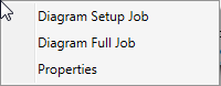
Using the Properties Command
Right-clicking the object and selecting the Properties command opens the definition for the selected Job or Dependency, allowing modification to be made that element.
Using Design Mode
Switching to Design mode (via the toolbar’s View dropdown) enables you to modify a Setup from within the diagram itself. This is done by dragging and dropping a menu of objects define new Setups, Jobs, Dependencies and Resources.
Specifically, Design mode enables the following features:
- Dependencies, Resources or Setups can be removed from a definition using a right-click option.
- Setups can be dragged from one step to another via its connectors.
- Opens a Symbols Palette to allow dragging of new Setups, Dependencies and Resources onto the diagram.

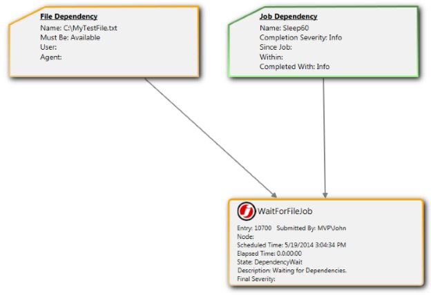
A Scheduled Job Diagram displays details for a scheduled Job and its Dependencies. This diagram is generated from the Monitor View or Gantt View on the JAMS Client.
- To create a Scheduled Job Diagram, open the Monitor or Gantt Views and right-click a Job.
- From the context menu choose the Diagram command.
Information Details
The Scheduled Job Diagram includes detailed information about the Job such as its current status including entry number, current elapsed time, if executed. Scheduling actions such as restarting or canceling a Job can also be controlled from the diagram using a right-click action.
The list below details some key information displayed on each object.
- Node: specifies the Agent Node that runs the Job.
- Current Step: indicates the current execution step for the Setup.
- State: shows current status of the Job.
- Final Severity: defines a Job's completion severity (e.g., Success, Informational, Warning, Error or Severe).
The Scheduled Job Diagram Toolbar
The Scheduled Jobs toolbar, located at the bottom of the diagram window, provides additional formatting controls that include:
- Layout: changes the current layout orientation for the diagram.
- Close Layer: closes the current layer if this is a subset of the original diagram. A layer can be opened by diagramming a Setup Job or Pre-Check Job from within a diagram.
- Print Preview: opens a print preview window and printing options for the current diagram.
- Refresh: refreshes the diagram information.
- Zoom: adjusts the diagram's zoom scale.

Object Color Indicators
Each element within the diagram displays a border color to identify the Job’s current state, e.g., an executing Job appears outlined in green and a pending Job displays within an orange border. These indicators also apply to a Pre-Check Job or any Dependencies within the diagram.